Rectifiers: AC to DC Current
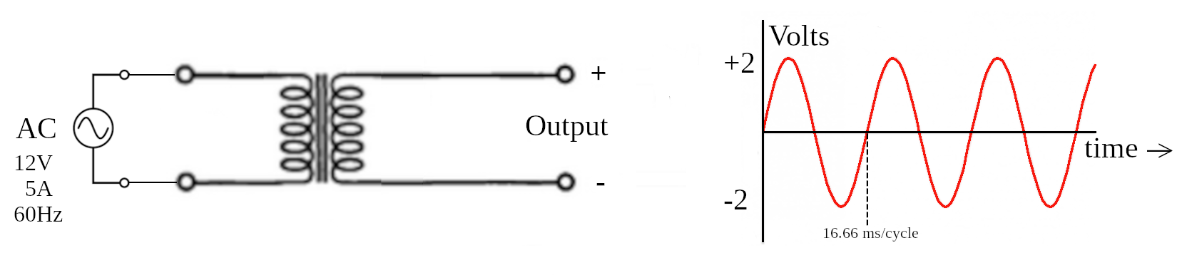
An AC source comes from a transformer that takes 120V from the wall outlet and produces 12V, 5A at 60Hz. This produces a sine wave on the oscilloscope with a peak positive of 2V and peak negative of -2V, with a cycle of 16.66 msec per cycle.
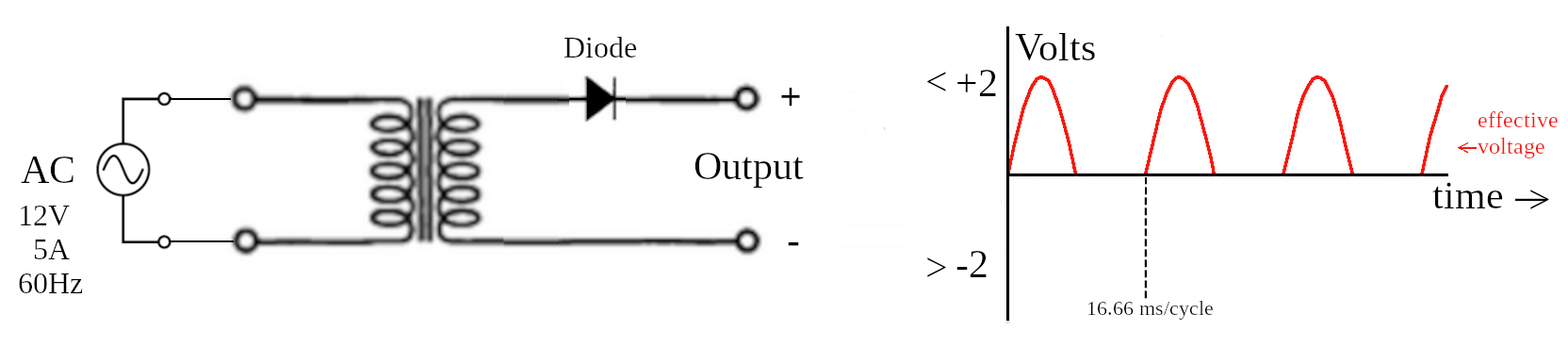
Placing a diode on the positive electrode produces a saw-tooth pattern. During the positive phase, the diode is forward biased and lets current through; however, when the diode is in the negative phase, it is reverse biased and does not allow any current. This produces an interrupted saw tooth pattern. The effective voltage is roughly 1/2 the peak voltage.
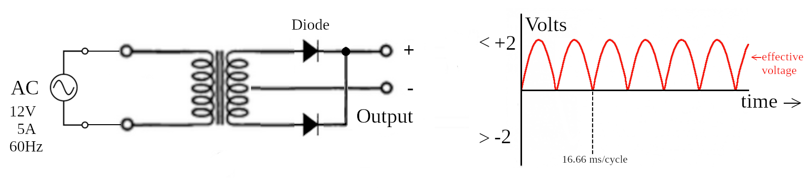
By tapping the center of the transformer and placing an extra diode on the second positive electrode, causing two separate forward biased currents. This creates a continuous saw tooth pattern. The effective voltage is about 2/3 the peak voltage.
Schematics

A Full-Wave Bridge Rectifier takes an AC power source without tapping the center and produces an uninterrupted saw tooth pattern. This is accomplished using a diamond-shaped pattern of diodes to break the positive and negative currents into two separate pathways.
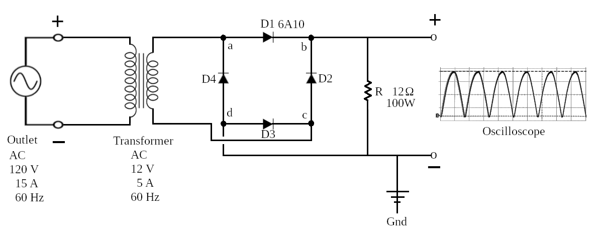
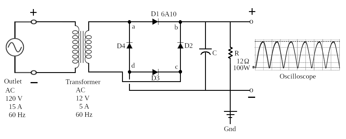
Schematic diagram of the circuit. Rather than draw the four diodes as a diamond, I chose to use a square since it is easier to configure a prototype with right angles. The resistor (R) gives the load required to prevent shorting the circuit.
Note: point b is the positive end (during the positive portion of the sine wave) and point d is the negative. These should be attached to the oscilloscope for measurement. Point a is attached to the positive lead of the transformer and point c is attached to the negative lead.
Measurements
| Resistor | A | V | W | Temperature |
|---|---|---|---|---|
| 6Ω-25W | 1.75 | 8.2 | 14.35 | Warm |
| 12Ω-100W | 1.60 | 9.0 | 14.4 | Hot |
Oscilloscope
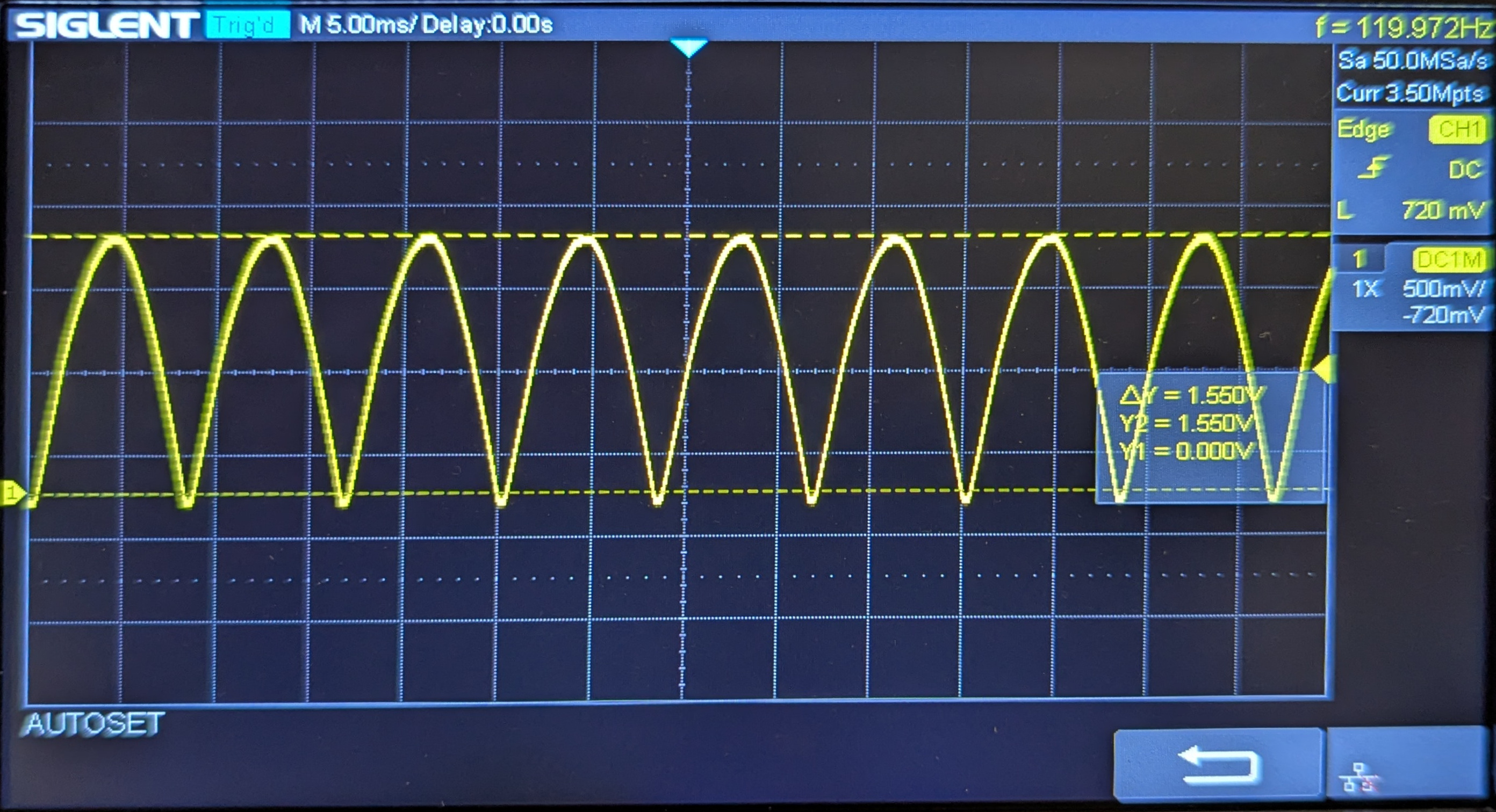
The voltage is recorded at 1.55V which is less than 2V due to diode D1. The effective voltages is approximately 1.03V, or 2/3 of the peak voltage.
Note: The voltage on the oscilloscope is only about 1/3 the voltage recorded using a voltmeter. Therefore, 1.5V on the oscilloscope is equivalent to 9V using the voltmeter (see the table below).
Table 1: Oscilloscope vs DC-Voltage Readings
Using only the 12Ω resistor| Voltmeter | Oscilloscope | ||
|---|---|---|---|
| Volts | ΔV | VPeak | VTrough |
| 12.0 | 4.0 | 2.0 | -2.0 |
| 9.0 | 3.0 | 1.5 | -1.5 |
| 5.0 | 1.7 | 0.8 | -0.8 |
| 3.3 | 1.1 | 0.6 | -0.6 |
| 2.0 | 0.7 | 0.3 | -0.3 |
Values are in volts.
Schematic #2
To modify the saw tooth pattern of the voltage, you can add a capacitor in parallel with the resistor. The capacitor works like an electric reservoir. It absorbs charge during the rising of the voltage, and releases charge as the charge drops.
Oscilloscope
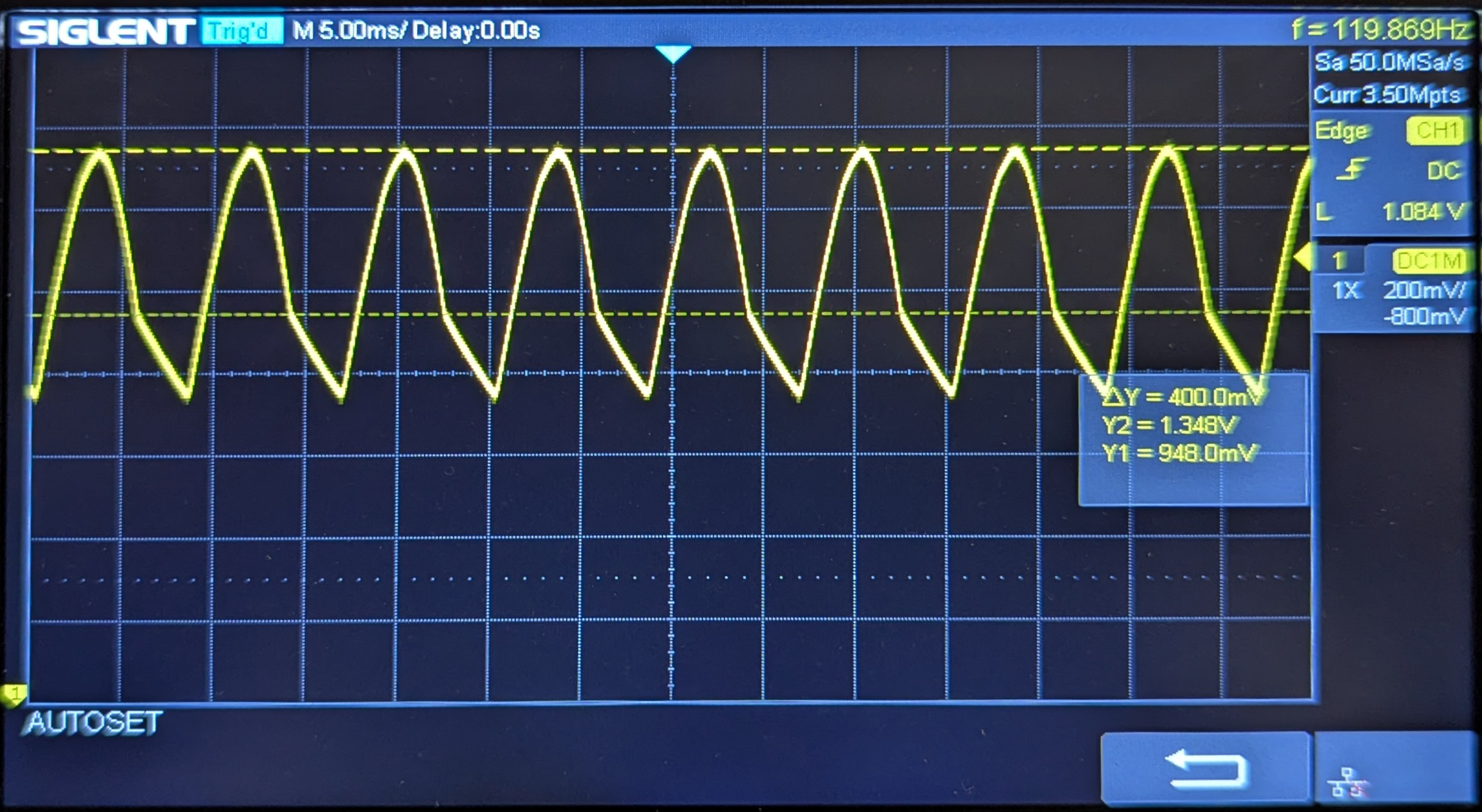
Using a capacitor rated at 16V 1000 uF. The top voltage is recorded at 1.348V.
Note: The zero voltage is at the very bottom, meaning that the saw tooth pattern is 'floating' near the top.
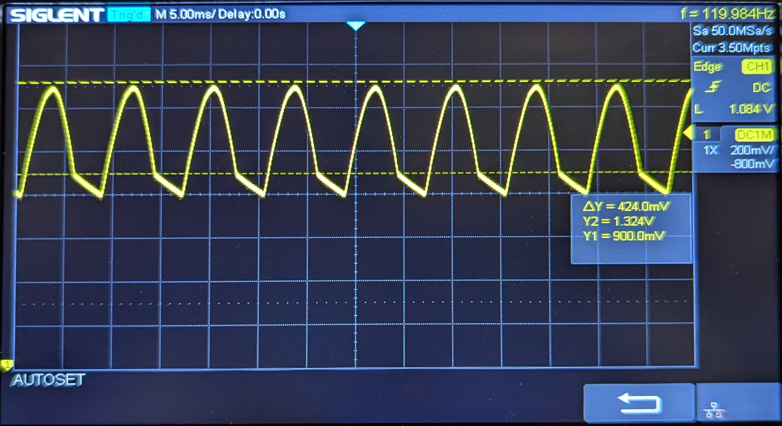
Using a capacitor rated at 10V 2200 uF. The top voltage is recorded at 1.324V.
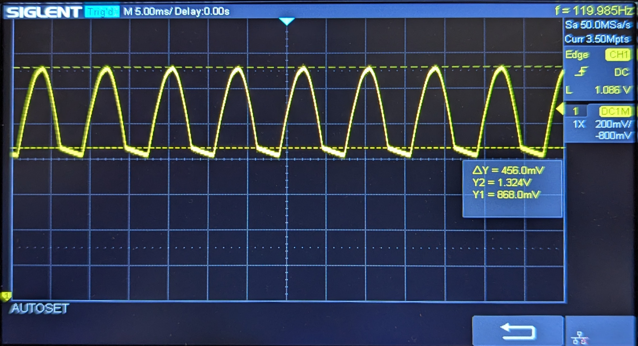
Using two capacitors in parallel, each rated at 10V 2200 uF (4400 uF total). The top voltage is recorded at 1.324V.
Note: the higher capacitance gives a flatter base. The ΔV and top voltage do not vary much.
Table 2: Oscilloscope Readings vs DC-Voltage
Using the 12Ω resistor and a series of capacitors in parallel| Cap[μF] | Y1[V] | Y2[V] | ΔY[V] | ⅓ΔY[V] | Eff[V] | DC[V] |
|---|---|---|---|---|---|---|
| 0 | 0 | 1.550 | 1.550 | 0.517 | 0.517 | 8.85 |
| 1000 | 0.948 | 1.348 | 0.400 | 0.133 | 1.081 | 10.22 |
| 2200 | 0.900 | 1.324 | 0.424 | 0.141 | 1.041 | 10.44 |
| 4400 | 0.868 | 1.324 | 0.456 | 0.152 | 1.020 | 10.20 |
where:
| Cap: | capacitor value |
| Y1: | bottom voltage |
| Y2: | top voltage |
| ΔY: | Y2 - Y1 |
| ⅓ΔY: | ⅓ x ΔY |
| Eff: | Effective voltage; Y1 + ⅓ΔY |
| DC: | Direct Current measured in volts |
Prototype
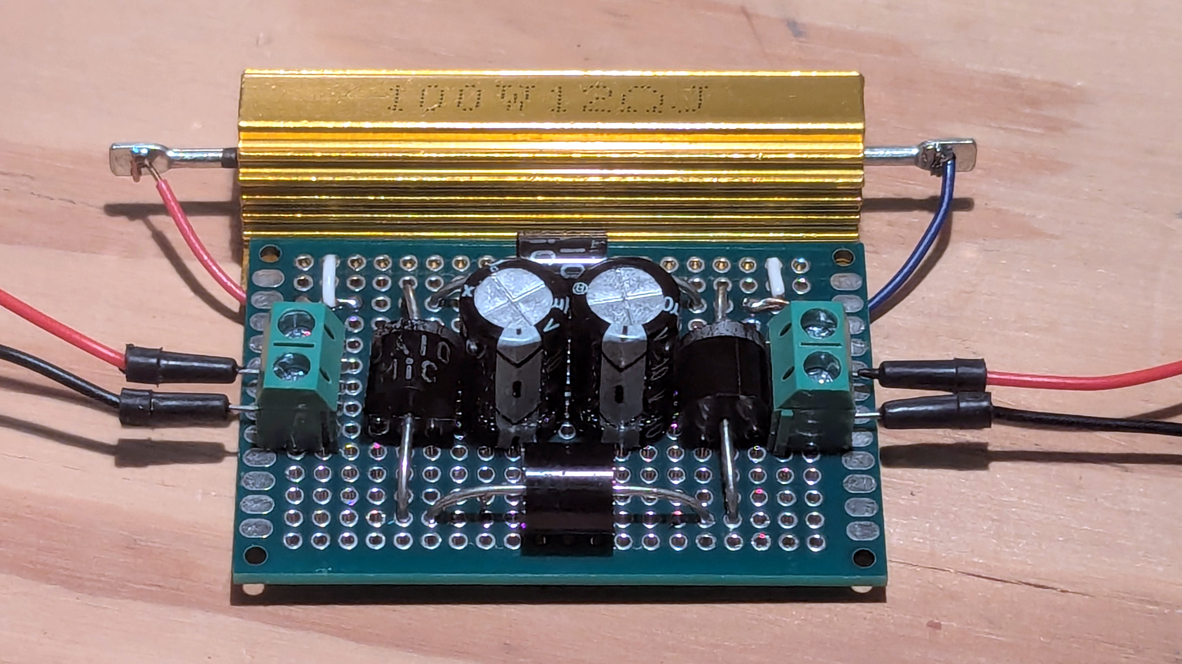
Using Schematic #2 (above), I have constructed this prototype. Looking from above, you can see the leads for the AC voltage coming from the left, the four diodes forming a square, the large 12 Ohm resistor (gold), and the two 2200 uF capacitors in the center. The DC current leads are to the right: red is positive and black is negative.
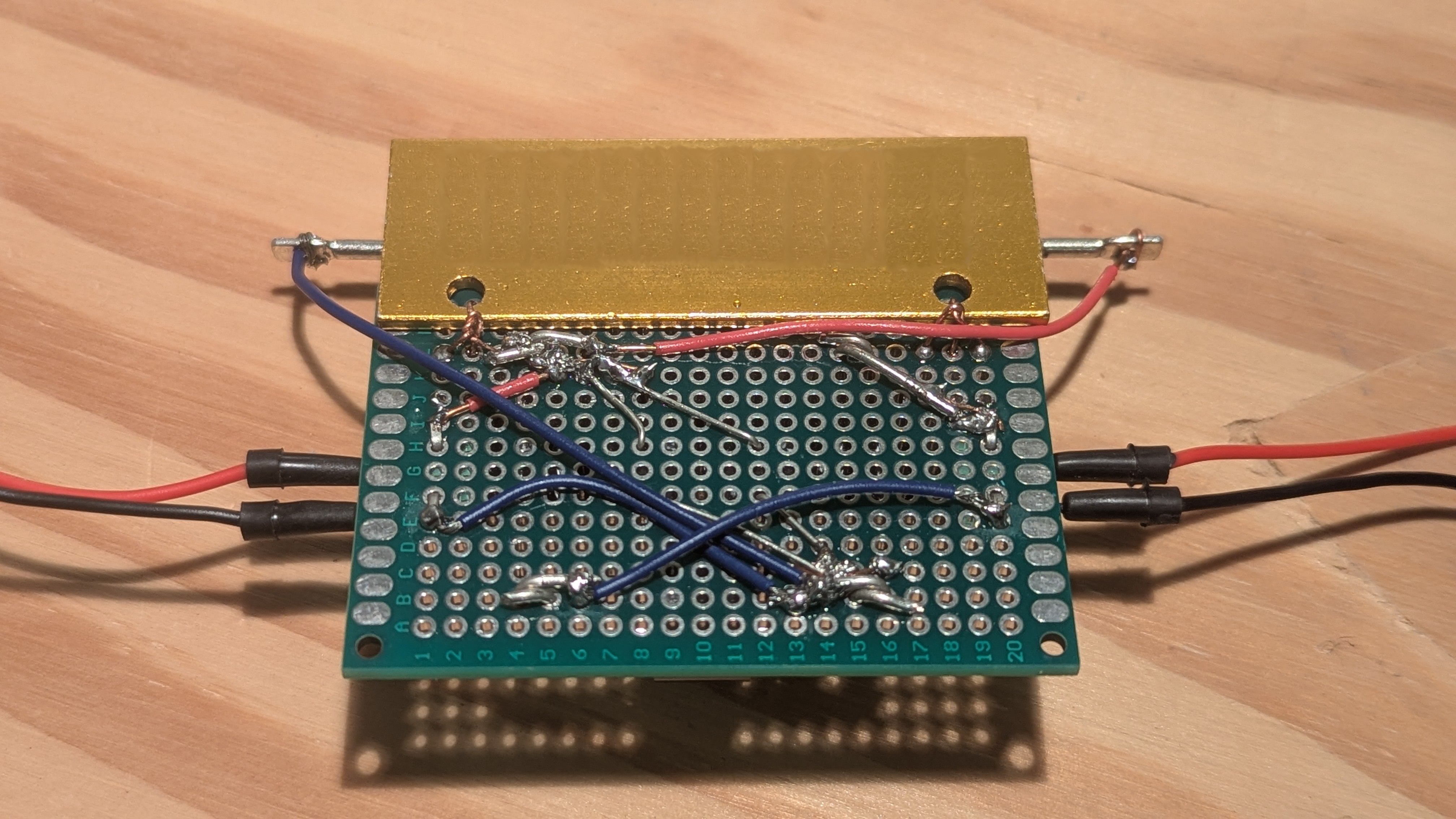
The back side showing the soldering and connections.
Oscilloscope: Final Display
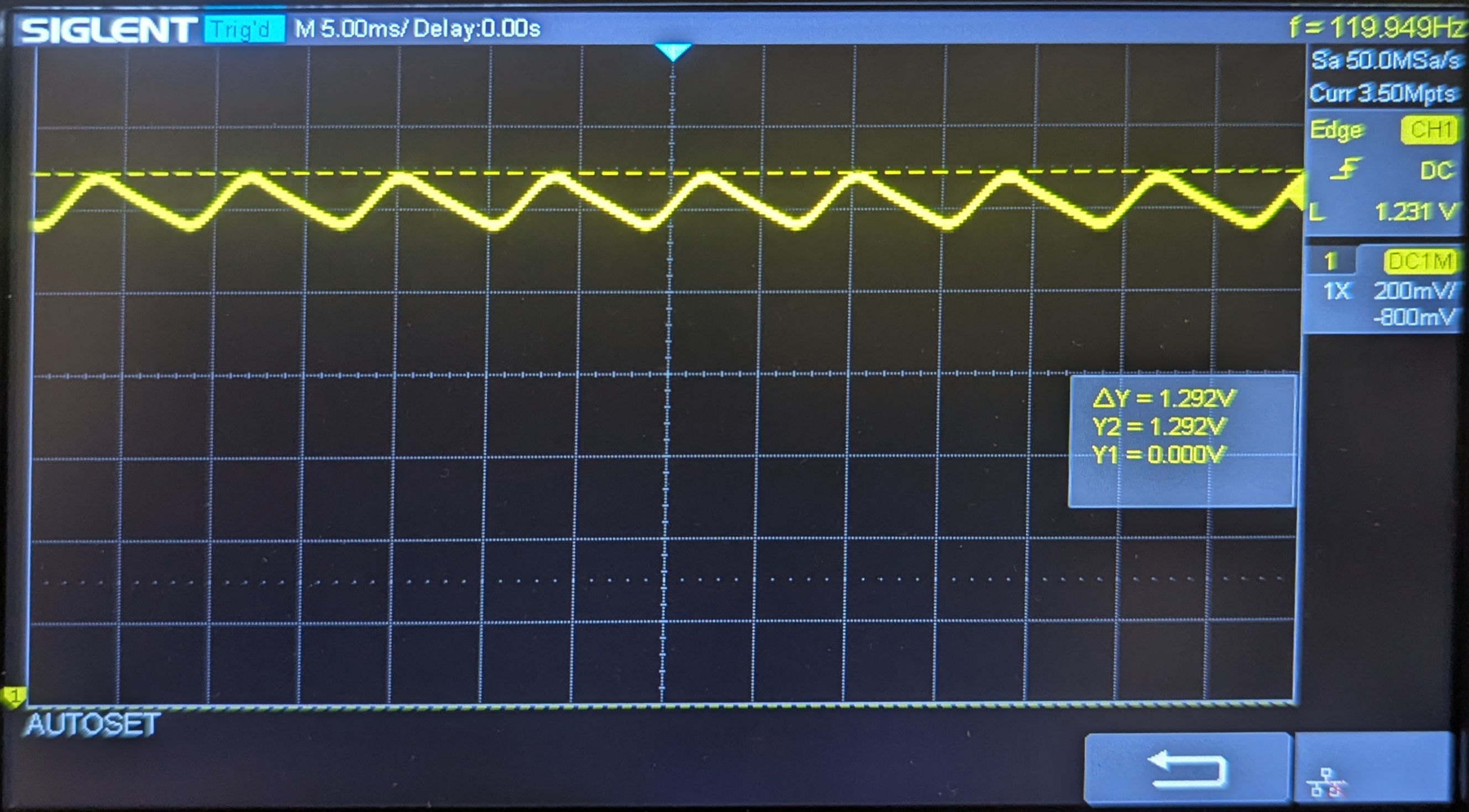 The final oscilloscope display shows a saw tooth pattern near the top just under 1.292V.